


GM
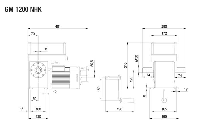
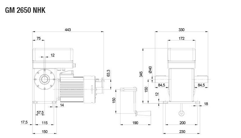
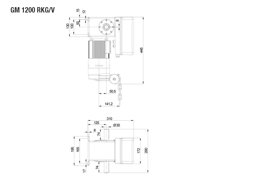
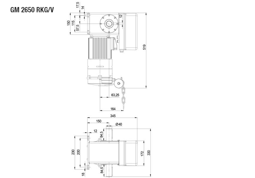
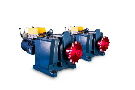
Worm-wheel operator Type GM 1200-2650
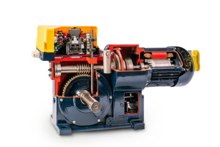
The operator:
Gear box with irreversible worm and worm-wheel. Two shafts with free ends, the wormwheel of special bronze and worm are equipped with ball bearings for noiseless operation. The worm-wheel of special bronze and worm are equipped with ball bearings for noiseless operation. The standard version has 30 revolutions at the drive shaft. The AC motor is directly with standard voltage 3-phase AC 230/400 V. (special voltage at options). All protruding shaft ends are sealed against oil leakage, so the unit can be mounted in any position: the horizontal position is recommended.
The limit switch
On the reduction is a box mounted with limit switch ES10, this can be connected with a separate controller which can be chosen out of the LST/WST range. The limit switch consist out of a potential free switch, a control current limit switch for the end positions and a safety switch for each side of rotation.
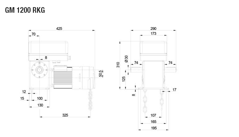
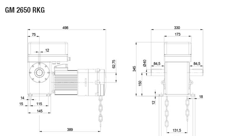
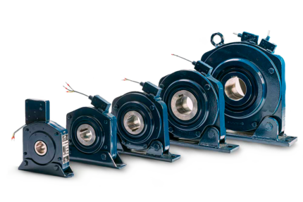
The Emergency chain operation
The RKG is mounted in front of the engine for a horizontal or vertical placement. Only one chain for manual operation. The integrated security switch avoids that the engine starts during the emergency operation. During the use of the emergency unit the end positions continue preserve.
Worm-wheel operator Type GM 1200-2650
| 1 | 2 | 3 | 4 | 5 | 6 | 7 | 8 | 9 | 10 | 11 | 12 | 13 |
|---|---|---|---|---|---|---|---|---|---|---|---|---|
| Type | Nm | Min-1 | U | kW | V | Hz | A | A | % | IP | Kg | dB(A) |
| GM 1200 | 120 | 33 | 30 | 0.55 | 230/400 | 50 | 2.8/1.6 | 10/6 | S3-60 | 44 | 22 | < 70 |
| GM 2650 | 265 | 30 | 30 | 1.1 | 230/400 | 50 | 4.8/2.8 | 20/10 | S3-60 | 44 | 34 | < 70 |
[save_as_pdf_pdfcrowd]
Worm-wheel operator Type GM 1200-2650
1. Type
2. Torque
3. Speed
4. Limit range
5. Motor power
6. Voltage
7. Frequency
8. Amperage
9. Fusing
10. Rating
11. Protection
12. Weight
13. Noise level in dB(A)
14. Weight of the gate
15. Chain wheel
16. Speed
17. Limit rang (larger limit range upon request)
(limit switch for longer lengths on request)
18. Pushing power
19. Control voltage
20. Mounting plate and protection hood
21. Initial lifting speed 20% friction included
22. Dimension of gate
23. Opening time
24. Width of wing max
25. Opening angle
26. Transformer
27. Dimensions and design subject to modifications
| GM 1200 | GM 2650 | |||||||||||
|---|---|---|---|---|---|---|---|---|---|---|---|---|
| 2:1 | 3:1 | 4:1 | 2:1 | 3:1 | 4:1 | |||||||
| Ø mm |
(1)* kg |
(2) cm/s |
(1)* kg |
(2) cm/s |
(1)* kg |
(2) cm/s |
(1)* kg |
(2) cm/s |
(1)* kg |
(2) cm/s |
(1)* kg |
(2) cm/s |
| 101.6×3.6 | 276 | 12.2 | 414 | 8.1 | 552 | 6.1 | 610 | 11.1 | 915 | 7.4 | 1220 | 5.5 |
| 108×3.6 | 264 | 12.7 | 396 | 8.5 | 528 | 6.3 | 584 | 11.6 | 876 | 7.7 | 1168 | 5.8 |
| 133×4 | 226 | 14.9 | 339 | 9.9 | 452 | 7.4 | 499 | 13.5 | 749 | 9.0 | 999 | 6.7 |
| 159×4.5 | 196 | 17.1 | 295 | 11.4 | 393 | 8.5 | 434 | 15.6 | 651 | 10.4 | 868 | 7.8 |
| 165.1×4.5 | 190 | 17.7 | 286 | 11.8 | 381 | 8.8 | 421 | 16.1 | 632 | 10.7 | 842 | 8.0 |
| 177.8×5 | 179 | 18.8 | 269 | 12.5 | 359 | 9.4 | 396 | 17.1 | 595 | 11.4 | 793 | 8.5 |
| 219.1×5.9 | 151 | 22.3 | 226 | 14.9 | 302 | 11.1 | 333 | 20.3 | 500 | 13.5 | 667 | 10.1 |
| 229×6.3 | 145 | 23.2 | 218 | 15.4 | 291 | 11.6 | 321 | 21.1 | 482 | 14.0 | 642 | 10.5 |
| 244.5×6.3 | 137 | 24.5 | 206 | 16.3 | 275 | 12.2 | 303 | 22.3 | 455 | 14.8 | 607 | 11.1 |
| 267×6.3 | 127 | 26.5 | 191 | 17.6 | 255 | 13.2 | 281 | 24.1 | 422 | 16.0 | 563 | 12.0 |
| 277×7.1 | 123 | 27.3 | 185 | 18.2 | 246 | 13.6 | 272 | 24.8 | 409 | 16.5 | 545 | 12.4 |
(1) Weight* (2) Initial lifting speed
*The armour weights indicated in the tensile force tables already include 20% friction and first rotation.
[save_as_pdf_pdfcrowd]
Worm-wheel operator Type GM 1200-2650
[save_as_pdf_pdfcrowd]


| Brand | Rolling doors |
|---|
Om meer info te zien dien je een login te hebben. Heb je nog geen login? Vraag hem hier aan.


 ROLLER DOORS
 ACCESSORIES